This post goes deep into customising menu structures for (AutoCAD and) BricsCAD. Organisations that use CAD always do so for specialised design work. It is therefore only logical to customise the CAD environment in terms of interface and custom commands. This post looks specifically at menu structures in the form of toolbars. For this, we look at so-called “custom user interface” or .cui files.
It is obvious to use the CUI command to cast buttons and commands into menus. There is more than enough information on the net on how to do this. However, it is important that you perform such work on a new partial menu. If you don’t, chances are that after an update of your CAD programme, all your efforts will be lost.
The CUI command is nice and all, but for serious work it is too limited. You’re better off taking a different approach then and that’s what this article is about. Menu files used to be .mnu files and at some point changed to XML files. Those XML files aim to be easily understood by both computers and humans. However, an XML menu file is soon many thousands of lines of code and thus the purpose is lost a bit. When working with XML files, use a proper editor, such as Notepad++. Such an editor recognises the structure, making it a whole lot easier for us humans to fathom.
A final introductory remark: I work at NedCAD and you can always outsource this kind of work to us.
Table of Contents
Summary
- It is not difficult to create XML for Customized User Interfaces for BricsCAD (and AutoCAD) in the form of .CUI files.
- This page, with all its seemingly technically difficult constructions, proves that it is not that complicated at all.
- The way described here works completely outside the CAD programme, giving a fair degree of independence.
- Do you use AutoCAD? See the section below.
- System administrators who need to maintain multiple or complex menu structures will find it considerably easier to do it this way, with all the benefits of quality and time savings.
Good luck!
Scope
The method we use can be widely used for numerous menu items, such as the ribbon and pop menus. Below, we will restrict ourselves to toolbars, i.e. buttons, button bars and fly outs.
Intermezzo MyMenu
I am trying to provide some relief by publishing typical formulas and content as copy-and-pasteable.
Some files:
- An ODS spreadsheet file MyMenu.ods. It is best to use LibreOffice for editing.
- A container with PNG files as MyMenu.zip. After downloading, rename this file to MyMenu.resz.
The tools
A structure is created using a spreadsheet. LibreOffice Calc is used for this purpose. Besides being “free software”, its advantage is that it is platform-independent and, if there are updates with problems, you can always fall back on previous versions. Over the years, LibreOffice Calc proves to be a very reliable partner for this work. However, make sure you turn off all (!!) well intended gimmicks found in menu > Tools > Autocorrect, just like spell checking.
In addition, an editor is desirable and on a Windows platform, Notepad++ is obvious. Make sure you have XML-tools as plug-in. If you want to be more platform-independent, Geany is a great alternative.
Workflow
Our custom-made menu is “MyMenu”.
A menu structure is defined in an XML file called “MyMenu.cui” (custom user interface). In that file are references to images of buttons. After editing MyMenu.ods, column I is pasted to a file MyMenu.cui.
Those buttons are bitmaps in a small and large variation of 16×16 and 32×32 pixels, respectively. Using PNG as the file format is sensible. All those bitmaps are put into a ZIP file “MyMenu.zip”. It is wise not to apply compression. After this, rename “MyMenu.zip” to “MyMenu.resz” (resource zipped).
Make sure “MyMenu.cui” and “MyMenu.resz” are in the search path.
Now use command CUILoad to load (and unload) the menu “MyMenu.cui”.
XML…
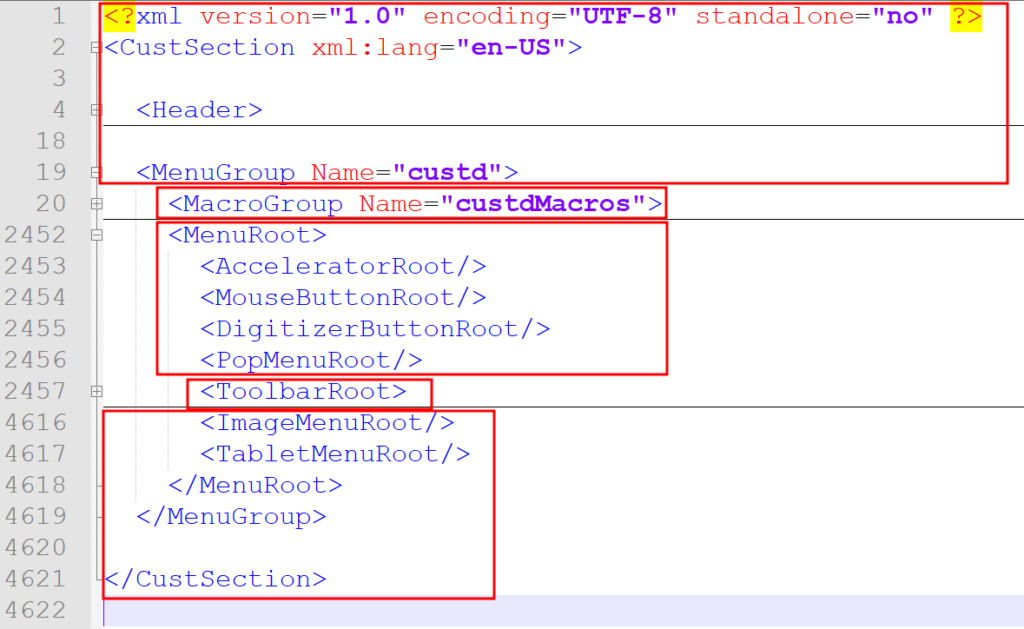
The XML file is made up of several parts that can be used to create complex structures. If we restrict ourselves to toolbars, the structure is as follows:
- Header, start
- Macros
- Intermediate
- Toolbars
- Footer, end piece
This screen dump illustrates the structure.
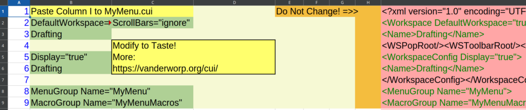
The sheet
The principle of the spreadsheet is that you use a number of columns for buttons and the structure (A-H), and to the right of these, one column (I) is reserved for the creation of XML code. That column can then be pasted into a .cui file.
The first column is an index, 1, 2, 3, … This is useful if you want to sort selections. If a sorting session ends with REF! errors, make sure you have the following setting in Calc:
Menu: Tools > Options… > LibreOffice Calc > General > Update references when sorting range of cells.
This is not a tutorial on Calc, minimal knowledge is required. If you are familiar with Excel then you are also familiar with Calc. You can also try it in Excel if necessary.
Header
The start of the document to macro definitions.
I1:
<?xml version="1.0" encoding="UTF-8" standalone="no" ?><CustSection xml:lang="en-US"><Header><WorkspaceRoot>
I2:
="<Workspace "&B2&" "&C2&">"
Etcetera
The complete start, for example, is:
<?xml version="1.0" encoding="UTF-8" standalone="no" ?><CustSection xml:lang="en-US"><Header><WorkspaceRoot>
<Workspace DefaultWorkspace="true" ScrollBars="ignore">
<Name>Drafting</Name>
<WSPopRoot/><WSToolbarRoot/></Workspace><WorkspaceConfigRoot>
<WorkspaceConfig Display="true">
<Name>Drafting</Name>
</WorkspaceConfig></WorkspaceConfigRoot></WorkspaceRoot></Header>
<MenuGroup Name="MyMenu">
<MacroGroup Name="MyMenuMacros">
Macros
Row 10 is the start of UIDs (B) with a tooltip (C) and a command (D). A snippet looks like this:
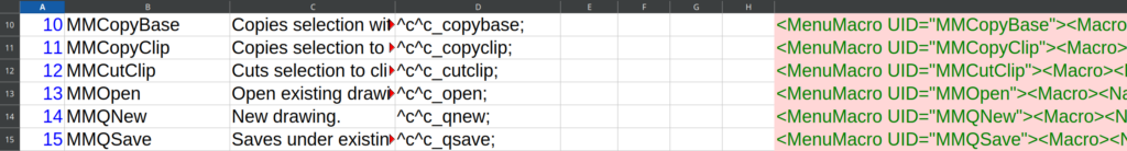
The formula of row 13:
I13:
="<MenuMacro UID="""&B13&"""><Macro><Name>"&C13&"</Name><Command>"&D13&"</Command><SmallImage Name="""&B13&"_16.png""/><LargeImage Name="""&B13&"_32.png""/></Macro></MenuMacro>"
As you can see, UIDs are used to name the image of the buttons. Also note the dual and triple escaped double quotes.
Intermezzo buttons
Tip: There is a video about creating buttons for toolbars in BricsCAD here.
We usually draw the buttons in BricsCAD in a grid of 16*16 drawing units. These are mostly closed polylines.
After exporting as SVG, the buttons are filled with colour in Inkscape and the line width becomes 0. Also, the size becomes exactly 32*32 pixels, corresponding to the “paper size”. The button is saved as UID.svg – in Inkscape it is SVG by default.
After this, the buttons are exported as UID_16.png and UID_32.png. For tool palettes, a size UID_128.png is also exported. You can do those steps for each button by hand.
Since we literally manage many hundreds of buttons, we use a BASH script for this purpose. That script generates all the buttons in PNG format based on the available SVG files. It uses Inkscape on the command line. Moreover, it puts the PNG files into a zip file (without compression!) and renames this zip file to MenuName.resz, ready to use together with MenuName.cui.
It is also good practise to keep UIDs in alphabetical order.
Intermediate
The line between the macros and the toolbars is small but important. Here’s a screen dump:

Line 16, B16 contains the text “ToolBars” and that returns in the form of an IF statement in the section “Toolbars” below.
Intermezzo pretty printing
The nice thing about XML is that the formatting, the indentation, can be done fully automatically and at the same time the computer is not interested in the formatting. This is also the reason why column I can be poured into a CUI file like this and BricsCAD reads it in without any problems.
After this, you see I16 as “one liner” and formatted
Notepad++: Menu > Plugins > XML Tools > etcetera
I16 begins with the end of MacroGroup and marks the start of ToolbarRoot.
I16:
</MacroGroup><MenuRoot><AcceleratorRoot/><MouseButtonRoot/><DigitizerButtonRoot/><PopMenuRoot/><ToolbarRoot>
Pretty:
</MacroGroup>
<MenuRoot>
  <AcceleratorRoot/>
  <MouseButtonRoot/>
  <DigitizerButtonRoot/>
  <PopMenuRoot/>
  <ToolbarRoot>
One final note, if the tags are looked at, you might conclude that this approach with a spreadsheet also opens up possibilities for things other than just toolbars….
Toolbars
The screen dump shows the structure where column B contains the name of the element. So it starts with “bar” and then all the ingredients follow until the next “bar”.
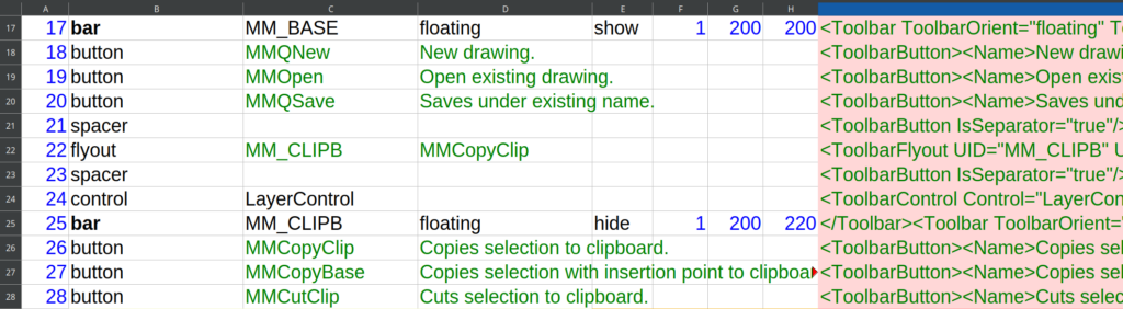
The screen dump shows the structure where column B contains the name of the element. So it starts with “bar” and then all the ingredients follow until the next “bar” entry.
What are the options for column B in this section?
- bar
- button
- spacer
- flyout
- control
Each entry has its own syntaxis, for more see “syntaxis” below.
Let’s have a look at the formula of I17:
=IFS(B17="bar",IF(B16="ToolBars","","</Toolbar>")&"<Toolbar ToolbarOrient="""&D17&""" ToolbarVisible="""&E17&""" UID="""&C17&""" rows="""&F17&""" xval="""&G17&""" yval="""&H17&"""><Alias>"&C17&"</Alias><Name>"&C17&"</Name>",B17="button","<ToolbarButton><Name>"&D17&"</Name><MenuItem><MacroRef MenuMacroID="""&C17&"""/></MenuItem>"&IF(E17="","","<State>"&E17&"</State>")&"</ToolbarButton>",B17="spacer","<ToolbarButton IsSeparator=""true""/>",B17="flyout","<ToolbarFlyout UID="""&C17&""" UseOwnIcon=""false"" pTargetAlias="""&C17&"""><FlyoutName>"&C17&"</FlyoutName><SmallImage Name="""&D17&"_16.png""/><LargeImage Name="""&D17&"_32.png""/></ToolbarFlyout>",B17="control","<ToolbarControl Control="""&C17&"""/>")Function IFS is a condition statement, just like Lisp function (cond …). There is a structure and with some linebreaks it boils down to this:
=IFS(

B17="bar",
IF(B16="ToolBars","","</Toolbar>")&"<Toolbar ToolbarOrient="""&D17&""" ToolbarVisible="""&E17&""" UID="""&C17&""" rows="""&F17&""" xval="""&G17&""" yval="""&H17&"""><Alias>"&C17&"</Alias><Name>"&C17&"</Name>",

B17="button",
"<ToolbarButton><Name>"&D17&"</Name><MenuItem><MacroRef MenuMacroID="""&C17&"""/></MenuItem>"&IF(E17="","","<State>"&E17&"</State>")&"</ToolbarButton>",

B17="spacer",
"<ToolbarButton IsSeparator=""true""/>",

B17="flyout",
"<ToolbarFlyout UID="""&C17&""" UseOwnIcon=""false"" pTargetAlias="""&C17&"""><FlyoutName>"&C17&"</FlyoutName><SmallImage Name="""&D17&"_16.png""/><LargeImage Name="""&D17&"_32.png""/></ToolbarFlyout>",

B17="control",
"<ToolbarControl Control="""&C17&"""/>"

)
There are two IF statements used that deserve some explanation.
Each “bar” is the end of the previous “bar”, so we can start with </Toolbar> except for the first one. That’s what the IF statement is for, the first “bar” starts normally, without </Toolbar>.
Optionally, for a “button” you can include Diesel code that affects the visibility of the button. See for example the standard buttons for object snap. That is what the second IF statement is used for.
Footer
The end looks like this:

The last “bar” definition is not closed so that is what I970 is for.
Now let’s finish it all. As XML code:
I29:
</Toolbar>

I30:
</ToolbarRoot>
<ImageMenuRoot/>
<TabletMenuRoot/>
<RibbonRoot>
  <RibbonTabSourceCollection/>
  <RibbonPanelSourceCollection/>
  <RibbonTabSelectors/>
</RibbonRoot>
<DoubleClickRoot/>
<QuadRoot>
  <QuadTabs/>
</QuadRoot>
</MenuRoot>
</MenuGroup>
</CustSection>

I30 as oneliner:
</ToolbarRoot><ImageMenuRoot/><TabletMenuRoot/><RibbonRoot><RibbonTabSourceCollection/><RibbonPanelSourceCollection/><RibbonTabSelectors/></RibbonRoot><DoubleClickRoot/><QuadRoot><QuadTabs/></QuadRoot></MenuRoot></MenuGroup></CustSection>
As you can see there are several roots here for for example ribbon and quad, tempting!
This is the end of the spreadsheet definition and I really hope it inspires. There are several tags used that need some clarification…
What about AutoCAD?
This post is about BricsCAD. What about AutoCAD?
Command “Options” provides a location for “Custom Icons” via the first tab. You need to rename the file “MyMenu.resz” discussed here to “MyMenu.zip” and extract it at that location.
Make sure “MyMenu.cui” is in the search path and load the “MyMenu.cui” menu using the “CUILoad” command. AutoCAD will then turn it into a compressed .CUIX file.
When you extract “MyMenu.cuix”, you can conclude that everything is in one file, i.e. XML plus PNGs. So the PNG files you extracted earlier can be deleted. Caveat: <State>, i.e. shading of buttons via Diesel code, is lost but that is probably not a concern in most cases.
Within the set of XML files you will find “Macros” in “MenuGroup.cui” again. The “Toolbars” section is in file “ToolbarRoot.cui”. The syntax is slightly different but translating MyMenu.cui to MyMenu.cuix goes pretty well in AutoCAD, producing the same set of toolbars and buttons.
In conclusion, you can therefore use the method described on this page very well for AutoCAD too.
Syntaxis
Spreadsheet
The sheet has a section with macros and then a section with toolbars. The description is based on the letters of the columns.
Macro section
The macro section has the following structure:
- A: Index (1, 2, …), only used for sorting
- B: UID, a unique CamelCaseName like MMQSave
- C: Tooltip, short help snippet.
- D: Command sequence, e.g. “Esc Esc Line enter” equals “^c^c._line;”
Toolbar section
This part is a bit more complex…
- A: Index for sorting
- B: Toolbar element
- bar
- C: Toolbar_Name, also UID and alias, no spaces
- D: Position: floating, top, left, right or bottom
- E: State: show or hide
- F: Rows: 1 (or more)
- G: X position in screen pixels, right is positive, origin is top left of screen
- H: Y position, as G, down is positive.
- button
- C: A macro UID. Best practise: create a reference to macro B, e.g. “=B44”
- D: Name, a reference is used here too, drag C value to right to get “=C44”
- E: Empty or a Diesel expression influencing button visibility “State”, see tag <State>.
- spacer
- No arguments
- flyout
- C: UID, reference to involved bar C value like “=C120”
- D: Shown first button, a reference to macro B, e.g. “=B55”
- control
- C: An existing control element, like “LayerControl”.
- bar
CUI XML Tags
Except for this attempt, there is no documentation to be found. It is all try and error and reverse engineering. That said, we’ve learned some things:
<ToolbarFlyout>
A central role for:
pTargetAlias=”STRING”
A flyout is an ordinary toolbar and is referenced in another toolbar as a flyout. pTargetAlias is the reference of the flyout that points to <Alias>.
Example:
<Toolbar ToolbarOrient="floating" ToolbarVisible="hide" rows="1" UID="OhSomeNotUsedName">
  <Alias>TB_SomeName</Alias>
  <Name>Some Name</Name>
and…
<ToolbarFlyout UseOwnIcon="false" pTargetAlias="TB_SomeName">
  <FlyoutName>Some Name</FlyoutName>
<State>
This tag influences visibility of buttons, provided that PNGs with an alpha-channel, transparent background, are used.
Diesel code can be placed between tags. An example from the toolbar entity snaps for the EndPoint button:
$(if,$(=,$(and,$(getvar,OSMODE),0x0001),0),,,!.)/.