How do you create button menus for BricsCAD (and AutoCAD) for your company without all the overhead of complex XML code? That’s what this article offers an answer to. AutoCAD – and by extension BricsCAD – uses XML for the definitions of the ribbon, menu bars and toolbars. XML files are intended to be readable by both humans and computers. Unfortunately, the emphasis is often on the latter and it is difficult to write XML from scratch. On top of that, the default menu contains almost 30 000 lines of XML, so customizations are not very straightforward to make. In the good old days before XML, menus looked very different. It was a simple text format with extension .mnu. The good thing is that both CAD systems can read .mnu files as partial menus. So we thought it would be nice to describe an example of this.
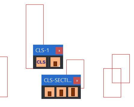
Table of Contents
First things first…
- This example is based on BricsCAD but in principle it is also applicable for AutoCAD.
- The term partial menu had already been mentioned. BricsCAD comes with numerous menus. If you’re going to change those then that’s fine…. until you get a new version with new menus. Therefore, it is better to work with separate corporate partial menus.
- We limit ourselves to toolbars.
Structure of a .mnu file
Although not difficult, it takes some getting used to the syntax. You can also see the following as a reference for later. We do it line by line…
You can indicate comments with one (or more) slashes. The first line of your file:
// This is corporate menu 1.
Then follows the section where all the toolbars are listed:
***TOOLBARS
After this the first “toolbarname” as a subsection:
**TEST_TOOLBAR
This is always followed by a line like this:
TAG [Toolbar("toolbarname", orient, visible, xval, yval, rows)]
The TAG is used as a reference to the HELP section. “Toolbarname” you already had (TEST_TOOLBAR). Orientation is often _Floating. Visible is _show or _hide. Xval and yval are the screen coordinates of the position in image pixels with the top left zero. Finally rows is usually 1.
Next, the toolbar is defined with a combination of buttons, flyouts, controls and spacers, respectively:
TAG [Button ("buttonname", small_icon.png, large_icon.png)]macro
TAG [Flyout ("flyoutname", small_icon.png, large_icon.png, icon, alias)]
TAG [Control (element)]
[--]
What you need to know is that two sizes of icons are used, 16*16 and 32*32 pixels. Macro, of course, is the command associated with a button. Icon you want as _OtherIcon. Alias is the reference to a subsequent toolbarname – after all, a flyout is a reference to a toolbar. Control are predefined interface elements like the layer pulldown.
That’s pretty much it and you can link the TAGs to help strings. So at the end follows section…
***HELPSTRINGS
… with lines like:
TAG [the help text]
An example for CLS
Canadian Lumber Standard (CLS) is what our menu is all about. More specifically: A toolbar with button to create a layer “cls” and a flyout with buttons to draw the dimensions 38*63, 38*88 and 38*140.
Buttons
You need four buttons in size 16*16 and 32*32 pixels for the layer and the three drawing commands. PNG is convenient.
One of the procedures for drawing buttons…. In CAD, draw the buttons in a grid, within a 16-unit square. You want closed polylines because you can fill them later. Then command Export and SVG format (AutoCAD does not support SVG, try via PDF). Open the SVG in Inkscape, Ctrl-U until everything is ungrouped. Select everything, Stroke style 0 width and Fill as Mesh Gradient. Now paste a button into an empty Inkscape document. Select everything and change X:, Y:, W: and H: to 0, 0, 32, 32 pixels(!) respectively. Ctrl-Shift-D and Resize… to Page or Document. Change the Fill as desired, drawing order (Home and End key). Finally, export as a PNG.
If all goes well then you will have 8 PNG files. From those files make a ZIP file. 7Zip is easy for this, select the files in explorer and choose (RMB, Right Mouse Button) Add to archive. Choose as name corp-1.resz, not corp-1.zip. Set compression to store, not normal. For AutoCAD you could put the icons in the custom icon folder.
The commands
For the layer and CLS drawings, the commands are respectively:
^c^c-layer;m;cls;c;1;;;
^c^c_point;\_erase;_last;;_pline;_non;@19,-31.5;_non;@0,63;_non;@-38,0;_non;@0,-63;c;
^c^c_point;\_erase;_last;;_pline;_non;@19,-44;_non;@0,88;_non;@-38,0;_non;@0,-88;c;
^c^c_point;\_erase;_last;;_pline;_non;@19,-70;_non;@0,140;_non;@-38,0;_non;@0,-140;c;
Some notes:
- Every enter is a semicolon. Type commands on the command line and count well 😉 .
- Every line starts with ^c^c, two times Esc-key.
- Having commands preceded by an underscore (_) makes it work even in localized versions.
- \ means: Wait for user input.
- _non is useful to avoid weird results because object snap is on.
- @ means relative to the last specified point.
- For the polylines this solution is very quick and dirty, there are better solutions than drawing a point first, removing it with the sole purpose of using the last specified point.
The menu file
Our file now looks like this. I think that is a lot clearer than the much larger XML file.
//  This is corporate menu 1 .
//  TAG [Toolbar("toolbarname", orient, visible, xval, yval, rows)]
//  TAG [Button ("buttonname", small_icon.png, large_icon.png)]macro
//  TAG [Flyout ("flyoutname", small_icon.png, large_icon.png, icon, alias)]
//  TAG [Control (element)]
// [--]
***TOOLBARS
**CLS-1
CLS-1    [_Toolbar("CLS-1", _Floating, _Show, 500, 500, 1)]
CLS-LAY  [_Button("Make layer CLS", cls-layer-16.png, cls-layer-32.png)]^c^c_-layer;m;cls;c;1;;;
         [--]
CLS-SECT [_Flyout("Draw CLS sections", cls-s-16.png, cls-s-32.png, _OtherIcon, CLS-SECTIONS)]
**CLS-SECTIONS
CLS-SECT [_Toolbar("CLS-SECTIONS", _Floating, _Hide, 500, 525, 1)]
CLS-S    [_Button("Draw CLS small", cls-s-16.png, cls-s-32.png)]^c^c_point;\_erase;_last;;_pline;_non;@19,-31.5;_non;@0,63;_non;@-38,0;_non;@0,-63;c;
CLS-M    [_Button("Draw CLS medium", cls-m-16.png, cls-m-32.png)]^c^c_point;\_erase;_last;;_pline;_non;@19,-44;_non;@0,88;_non;@-38,0;_non;@0,-88;c;
CLS-L    [_Button("Draw CLS large", cls-l-16.png, cls-l-32.png)]^c^c_point;\_erase;_last;;_pline;_non;@19,-70;_non;@0,140;_non;@-38,0;_non;@0,-140;c;
***HELPSTRINGS
CLS-1    [CLS Toolbar 1]
CLS-LAY  [Create layer CLS and set current]
CLS-SECT [CLS Sections]
CLS-S    [CLS Section 38*63]
CLS-M    [CLS Section 38*88]
CLS-L    [CLS Section 38*140]
The directory of customizations
Corporate modifications you want in a separate directory, possibly on a network drive so everyone can use it. You then need to make sure that BricsCAD also knows where that directory lives. Therefore:
SFSP, Search File Support Path, is what you need to modify. In other words, this is the search path of your CAD program. Enter command Settings > Program Options > Files > Search File Support Path > add a directory.
You have the files corp-1.resz and corp-1.mnu. You put those in that directory.
Loading the menu
Now run command CuiLoad. Browse and choose file corp-1.mnu – note file types. There are the buttons!
You can start testing. In case of errors, modify the .mnu file and do CuiLoad > Unload > Load.
You will see that in the directory there is also a file corp-1.cui added. This is the XML file.
In conclusion
This was a brief introduction to creating button menus. Of course, there is much more to be said about it but a brief search on the net will quickly yield many answers. It cannot be emphasized enough how important it is to implement interfacing and standardization for CAD within your company. It is both funny and special that a technique that is decades old still has value. Of course we can also offer support in implementing enterprise standardization.